Remote temperature and humidity monitoring with ESP8266 and Blynk app
It was my first project with ESP8266 chip. I have just built a new greenhouse near my house and it was interesting for me what is going on there during a day? I mean how temperature and humidity changes? Is the greenhouse ventilated enough? So I decided that ESP8266 with DHT22 sensor is a good solution. Next question was, how to monitor the data from the sensors. After a while, I found that Blynk is a perfect app especially for a beginners or non-professional people who wants to build a project for the Internet of Things (IoT). .You can read more about Blynk here.
Next I found on the internet exactly such a project as I needed. So yes, it is not my idea. :) . The project I replicated is here. It was not so easy for me like for a beginner , but I managed to do it.
So for this project you will need.
Hardware
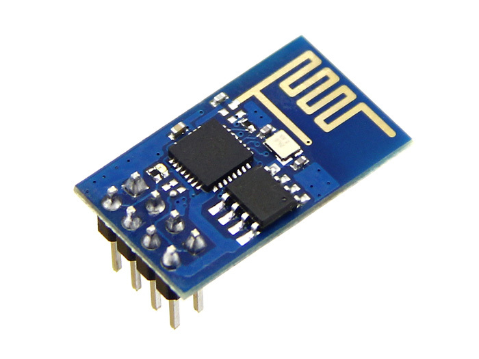
1. ESP8266-01 module like this one below:
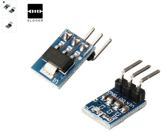
2. TTL converter or dedicated programming board for ESP8266. I am using programming board for ESP8266-01 like this:

3. DHT22 (AM2302) - temperature and humidity sensor:

4. Voltage converter.
For the ESP modules to be powered, a DC voltage of 3.0V-3.6V is required. Ideally, 3.3V. ESP can be powered from batteries or from a network, by converting AC 220V to DC. In any case, an additional voltage converter will be needed, to manage 3.3V DC voltage.
For example, a fully charged 18650 lithium-ion battery gives us up to 4.2 V. Such voltage most likely will kill ESP module. That is why we need a converter.
If input voltage is not exceeding 10V DC you can use for instance converter based on AMS117 chip:
5V To 3.3V DC-DC Step-Down Power Supply Buck Module AMS1117 800MA
or if the input voltage is higher so called "step-down" converters is the solution:
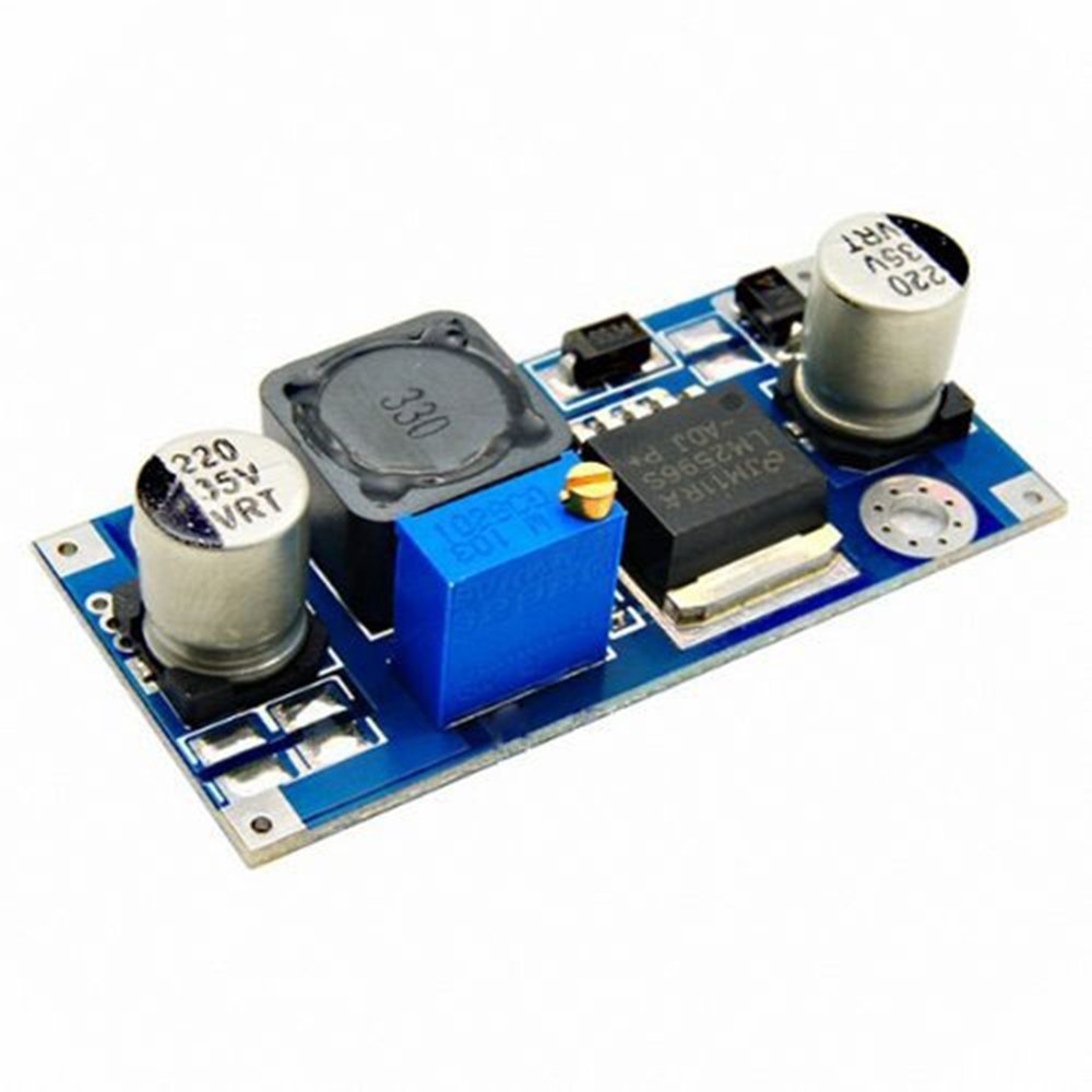
You can buy it on Amazone/eBuy/ Aliexpress:
https://www.amazon.com/RioRand-LM2596-Converter-1-23V-30V-1Pcs-LM2596/dp/B008BHAOQO
Because of I was using 12V acid lead battery, so I was forced to use step-down converter like this one above. Yes, now I know that it wasn't a best solution :). I think today I would choose 18650 li-ion batteries connected in parallel.
5. Power supply.
Like I mentioned above I used 12V acid lead battery for this project. It happened only because of I had one spare battery on the shelf. So of course you can use any power supply you want. Only keep in your mind that ESP chips accepts voltages from 3.0 to ,3.6V.
Diagram
The diagram is very simple. Just connect everything like it is shown below.

Software
To build the project, you need to install on your personal computer a program that allows you to flash the module. ARDUINO IDE is very suitable for this - the software development environment for ARDUINO components. ESP8266 is ARDUINO compatible module, so you can use it to program the ARDUINO IDE. The data is transferred to the phone by using Blynk application.
ARDUINO IDE
Download ARDUINO for your operating system. I am using ARDUINO 1.8.3 on my PC with Windows 10. After installation of ARDUINO IDE, you need to configure it, for using with ESP8266 chips.
So, open IDE:
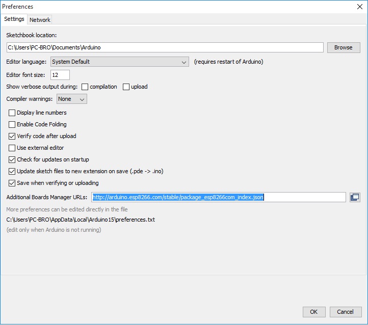
1. File - Preferences. On Preferences tab add the link: http://arduino.esp8266.com/stable/package_esp8266com_index.json,
This way, we add the ESP8266 to the list of equipment that IDE works with.
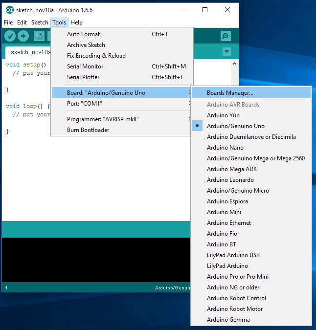
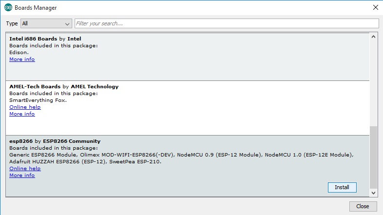
2. Tools - Boards - Boards manager
In the Board manager look for something like "ESP8266 by...". Click to install.
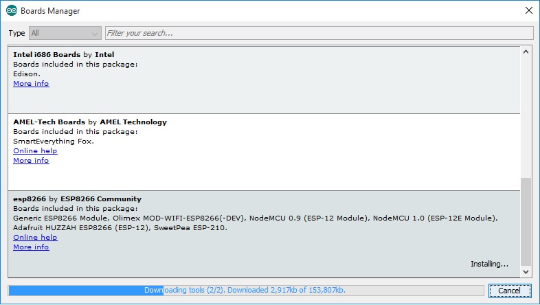
 Waiting...
3. Now we can see our 8266 board in the list. Choose it from the drop-down list
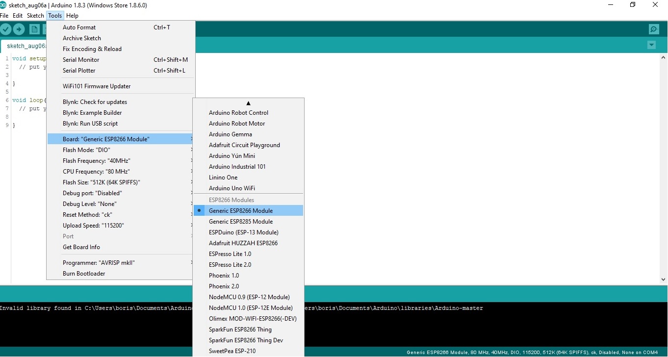
4. Choose the port on which we will work
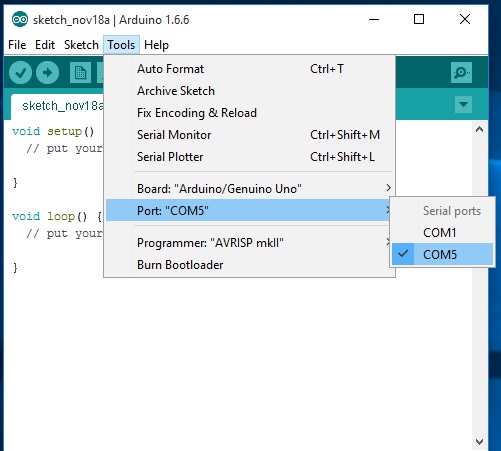
Yes, by the way, in Tools choose upload speed 11520.
5. Install libraries for ESP and Blynk.
Library for ESP could be found here. Push Clone to download.
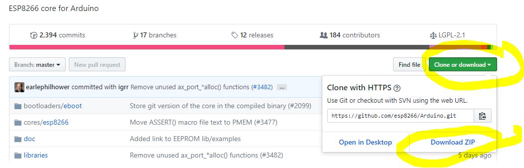
As soon as it would be downloaded, unpack it to the Arduino - Libraries folder.
BLYNK
So again, we need a library :). Download it from here. How to install here.
After you have installed library for Blynk, you will need an app for your phone. Download and install Blynk app from Google Play for Android, or from App Store for iPhone. Of course must have your account on Blynk to use it. After you have installed Blynk, login to the app and push "Create new project". You will get in your mailbox so-called "Auth token".

Next, enter the name of the project, for example "ESP8266". In the "Hardware model" field, you must select the type of device to work with. In our case this is ESP8266. And the last thing you have to enter is "Auth token".
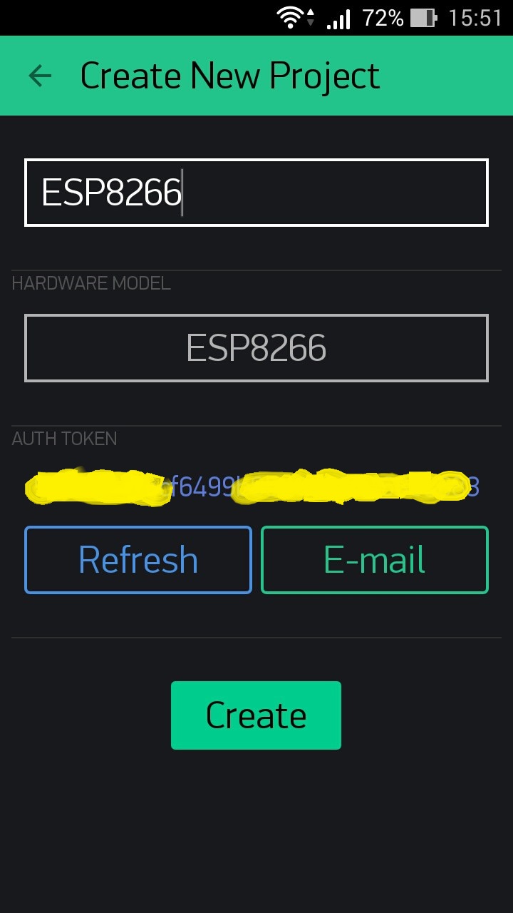
The "Auth token" is a secret key which is used during the connection with Blynk server. So do not share it with anybody. After clicking the "Create" button, the field for the graphical interface of your application will appear.

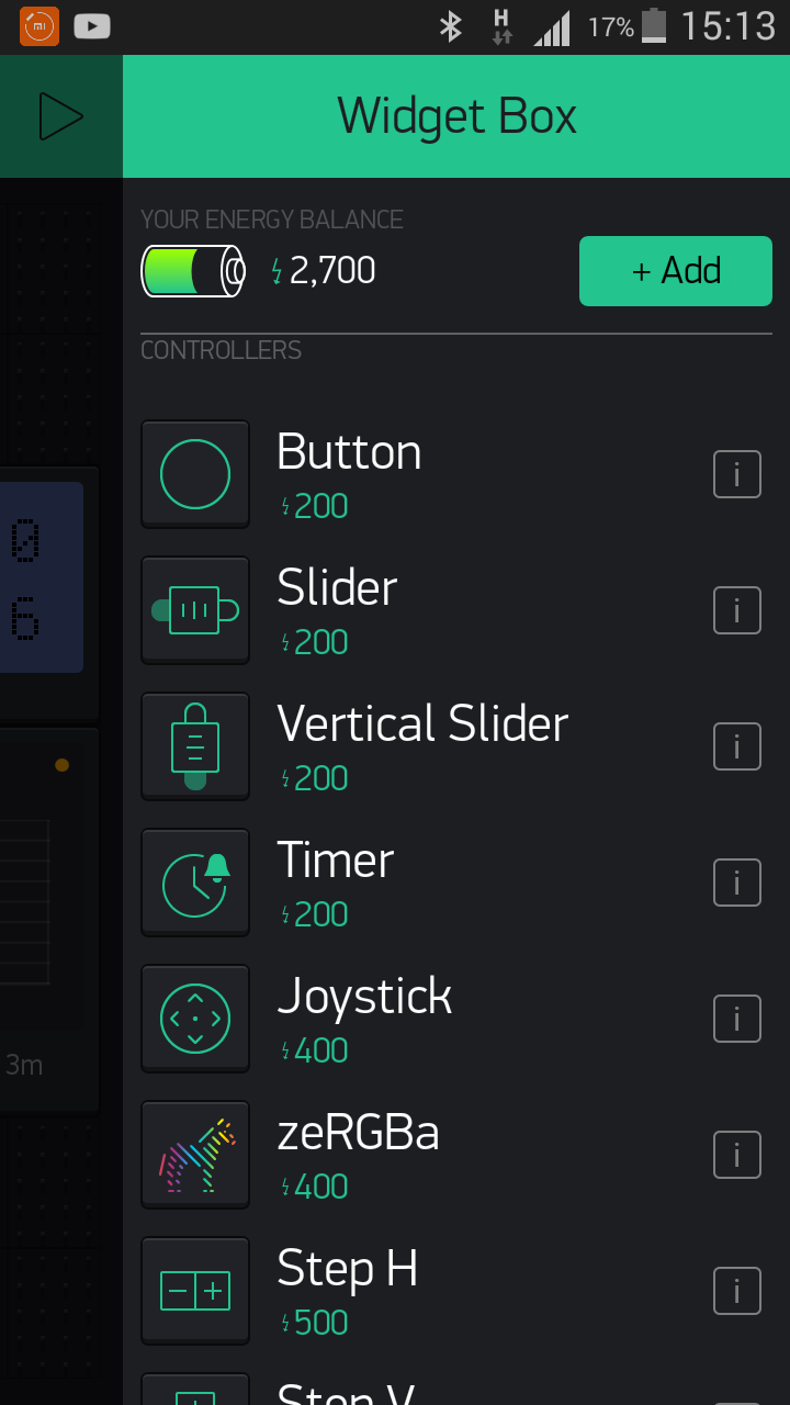
Click on the plus sign at the top right - the "Widget Box" toolbar will appear. It allows to add widgets to your control panel.
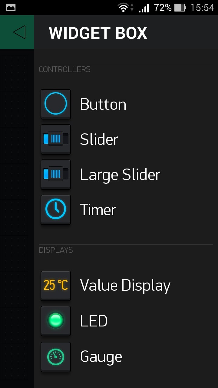
Looking ahead, I will say that our project will need widgets: "Button", "LCD" and "History graph".
Let's say it was the general part. All of this is useful for any project ESP8266 / Blynk.
ARDUINO sketch
So let's write a sketch. To do this, we use the previously mentioned Arduino IDE.
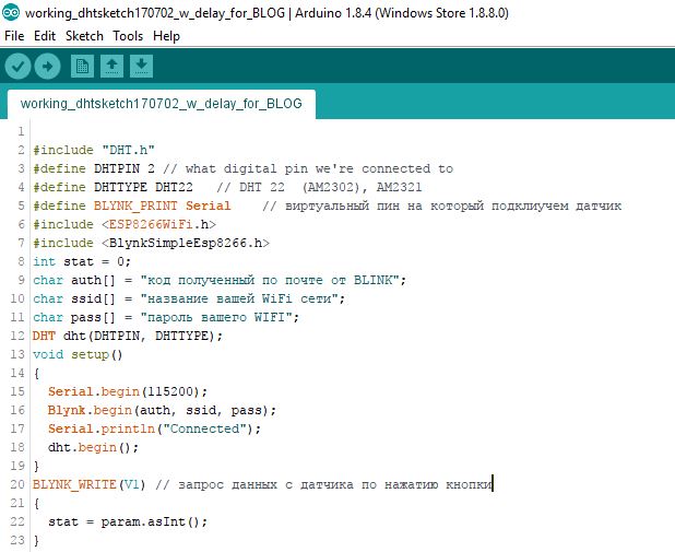
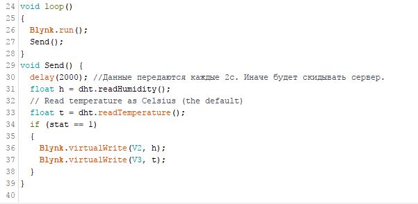
If you are going to power the device from the battery, then in line 30, it makes sense to play with the "delay"value. In this sketch, the data is transferring every 2s. Increase dealy time on line 30, to increase the battery life of you device. For example if you will put 300 000 here, data will be transferred every 5 min.
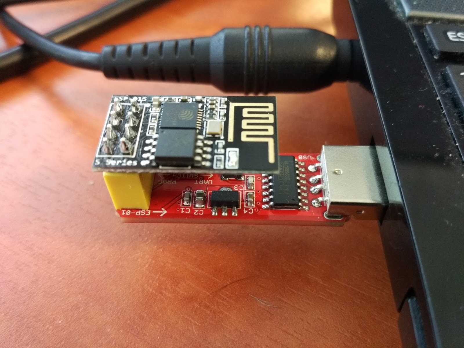
Next, plug the ESP8266 module into the TTL converter as shown in the photo below, and connect it to the USB port. If you have the same converter as me, then by itself you need to change the switch to the "Prog" position.
Run the Arduino IDE, and upload the sketch: file - open - your sketch.
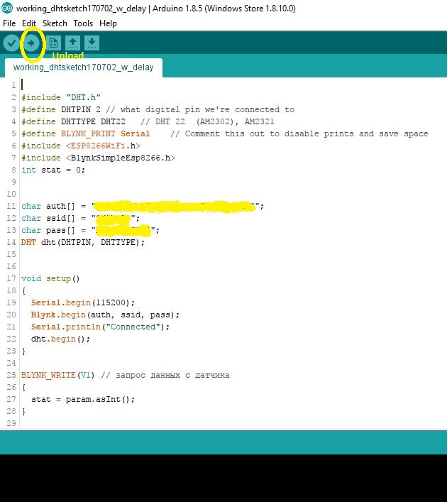
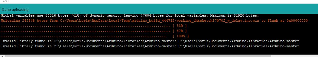
Click the "upload" button ( in a yellow circle on the photo). If the firmware download process was successful, the message "Done uploading" appears below.
Below you can see the progress of the upload. There may be reports of incorrect libraries, as on the photo. But latter I found out that everything is working. So the advice is - upload the firmware, check it will probably work.
Make Blynk application
Well, the last step, let's the application on Blynk.
So open Blynk, and in the "Widget Box" toolbar, select the "Button" widget.
A virtual button will appear on the application desktop. Click it, and get into the settings (see photo).
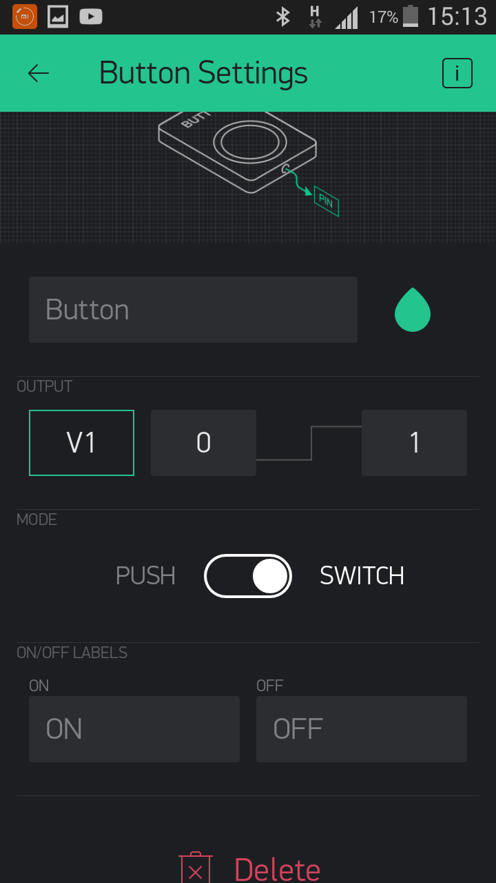
I have set a button to "Switch". It means the data is transferred while the button is switched on. As soon as the button is switched off, data transfer stops .You can enable "Push" mode. In this case, the data will be transmitted while the button is pressed with a finger. V1 is a virtual button port. Must coincide with the one indicated in the sketch. You can also specify the text that will be displayed on the button in the on position. and off.
Next, from the widgets, select the LCD. Again, go to the settings.
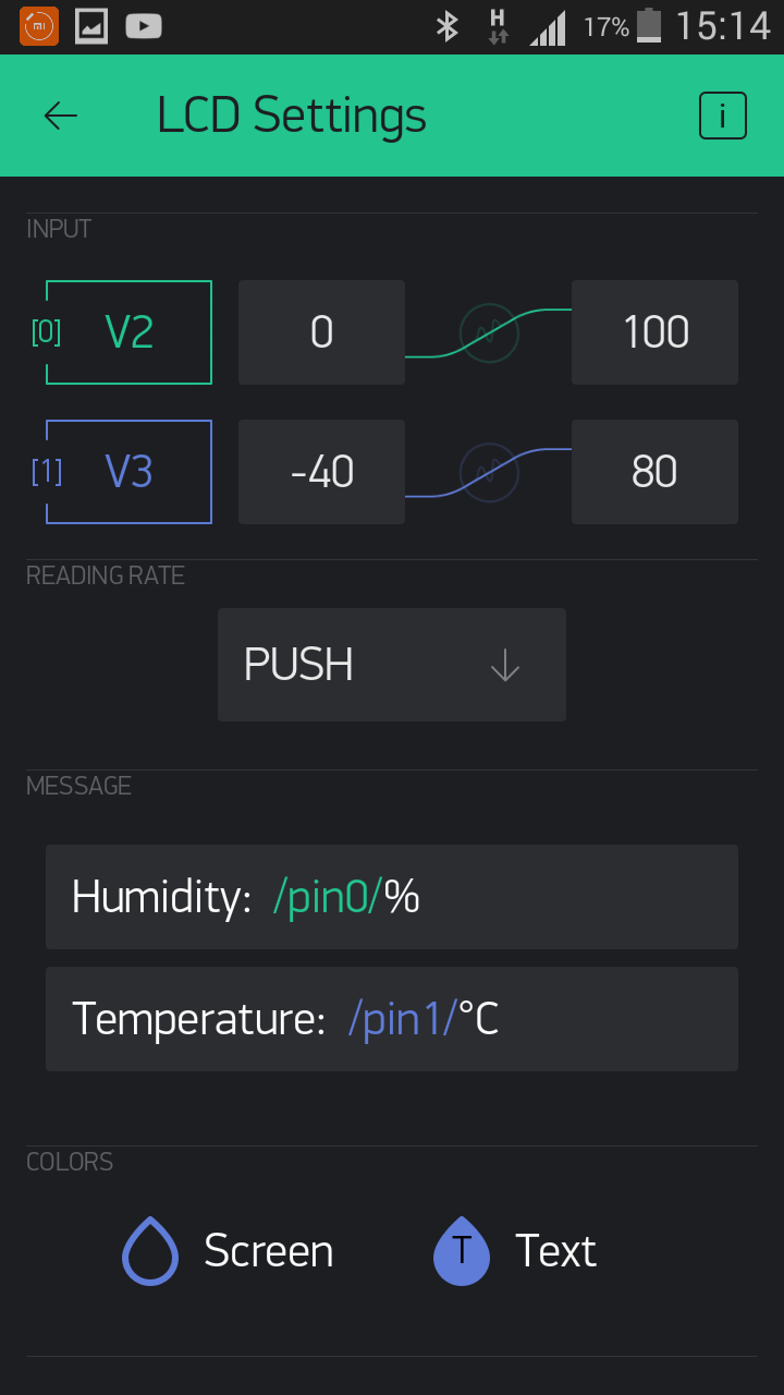
Set the temperature and humidity limits (V2 and V3) and the PUSH mode.
Of course it's interesting to see the history of the sensors. Here you can use the widget for plotting - "History Graph".
Customize the widget:
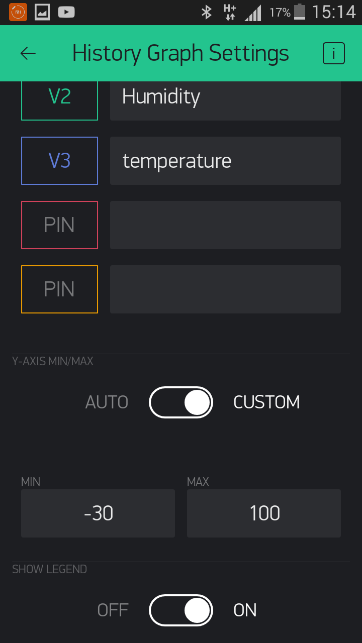
Everything is pretty clear here, I hope. We indicate that we want to see the boundaries along the axes.
The finished application looks like this:
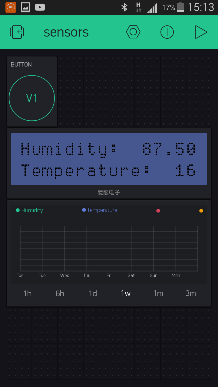
Press the triangle in the upper right corner, and if everything is done correctly, after a few seconds there will be readings from the sensors, and later the graphs will appear.
Later I will publish simple scheme how to connect all hardware for this project.
_______________________________________________________________________________________
Some usefull links:
http://www.whatimade.today/esp8266-easiest-way-to-program-so-far/
https://www.instructables.com/id/Get-Started-with-ESP8266-Using-AT-Commands-NodeMCU/
https://www.instructables.com/id/ESP8266-12-blynk-wireless-temperature-e-humidity-D-1/
http://www.forward.com.au/pfod/ESP8266/GPIOpins/ESP8266_01_pin_magic.html